


- 1
- 2
- 3
- 4
- ���F(xi��n)�ڵ�λ�ã� ��EDA�W(w��ng) >> CST >> CST�O(sh��)Ӌ(j��)��(sh��)�� >> ����
CSTͬ�S�������ķ����O(sh��)Ӌ(j��)������CST2013�O(sh��)Ӌ(j��)��(sh��)��
Draw the Air Parts
In this structure, the air can be easily modeled by uniting two rotational symmetric parts (a figure of rotation and a cylinder) as shown in the following diagram:
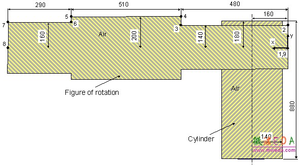
In the first step, you can begin drawing the figure of rotation. Because the cross section profile is a simple polygon, you do not need to use the curve modeling tools here (please refer to the CST STUDIO SUITE Getting Started manual for more information on this advanced functionality). For polygonal cross sections it is more convenient to use the figure of rotation tool, activated by selecting Modeling: Shapes > Extrusions > Rotate .
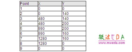
Since no face has been previously picked, the tool will automatically enter a polygon definition mode and request that you enter the polygons points. You can do this by either double-clicking on each points coordinates on the drawing plane or entering the values numerically. Since the latter approach may be more convenient, we suggest pressing the Tab key and entering the coordinates in the dialog box. All polygon points can thus be entered step-by-step according to the following table. Whenever you make a mistake, you can delete the most recently entered point by pressing the Backspace key. Arbitrary changes can also be made at the end of the input process.
After the last point has been entered, the polygon will then be closed. The Rotate Profile dialog box will then automatically appear.
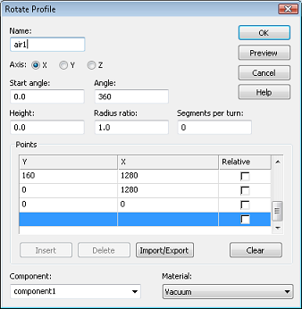
This dialog box allows you to review the coordinate settings in the list. If you encounter any mistakes, you can easily change the values by double-clicking on the incorrect coordinate entry field.
The next step is to assign a specific Component and a Material to the shape. In this case, the default settings with component1 and Vacuum are practically appropriate.
Please note: The use of different components allows you to collect several solids into specific groups, independent of their material behavior. However, here it is convenient to construct the complete connector as a representation of one component.
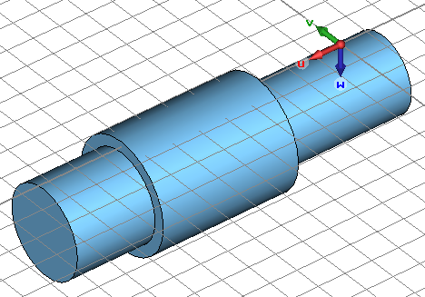
Finally, assign a proper Name (e.g. air1) to the shape and press the OK button to finish the creation of the solid. The picture below shows how your structure should appear:
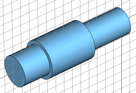
Construction of the second air part by creating a cylinder can be simplified if a local or rather working coordinate system (WCS) is introduced first. You can activate the working coordinate system by selecting Modeling: WCS > Local WCS. Afterwards, the origin of this coordinate system should be moved by selecting Modeling: WCS > Transform WCS. The following dialog box allows you to enter a vector along which the origin of the working coordinate system will be moved.
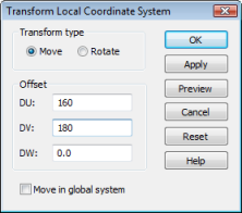
You should shift the origin by 160 mil along the u direction and by 180 mil along the v direction in order to position the WCS at the center of the cylinders base. Afterwards, rotate the WCS along its u-axis by 90 degrees. Therefore select Modeling: WCS > Transform WCS and define Rotate +90�� around U axis or using the shortcut Shift+U. The model should then look as follows:
The second air part can now be created using the cylinder tool: Modeling: Shapes > Cylinder . Once the cylinder creation mode is active, you are requested to pick the center of the cylinder. Because this is now the origin of the working coordinate system, you can simply press Shift+Tab to open the dialog box for numerically entering the coordinates and confirm the settings by pressing OK (please note that holding down the Shift key while pressing the Tab key opens the dialog box with the coordinate values initially set to zero rather than the current mouse pointers location).
You are now requested to enter the outer radius of the cylinder. Please press the Tab key again and set the Radius to 140 before pressing the OK button. The Height of the cylinder can then be set to 880 in the same manner. Skip the definition of the inner radius by pressing the Esc key (the air should be modeled as solid cylinder here) and check your settings in the following dialog box:
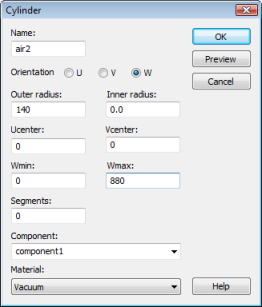
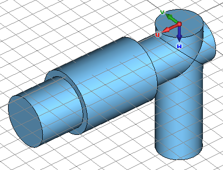
Finally, set the Name of the cylinder to air2 and verify that the solid again is associated with the vacuum Material. Confirm your settings by pressing OK. Since the two air parts overlap each other, the shape intersection dialog box will open automatically, asking you to select a Boolean operation to combine the shapes. Please select the operation Add both shapes to unite both parts and press the OK button. Your model should then finally look as follows:
-
CST����ҕ�l�̳̣��Y����v�⣬ҕ�l������ʾ���Ļ��A(ch��)�v��ѭ��u�M(j��n)�����Y(ji��)�����¹��̰������������ٌW(xu��)��(x��)����CST���O(sh��)Ӌ(j��)��(y��ng)��...��Ԕ��(x��)��B��
- CST�쾀�O(sh��)Ӌ(j��)���쾀��O(sh��)Ӌ(j��)��CST2013�O(sh��)Ӌ(j��)��(sh��)��
CST�C��ǻ�w�O(sh��)Ӌ(j��)������CST2013�O(sh��)Ӌ(j��)��(sh��)��
ʹ��CST���������M(j��n)��TDRӋ(j��)�����
CST�cMatlab�B���O(sh��)��
CST�������Һ�Agilent ADS �f(xi��)ͬ�����B���O(sh��)��
CST�������Ҳ鿴VSWR�Y(ji��)��
CST��������Y(ji��)������c�ⲿ��(sh��)��(j��)�M(j��n)�б��^
CST�������Ҳ��õ���Ҫ�㷨
ʹ��CST�������ҵĕr(sh��)�����������늴��}��
늴ż��ݵĔ�(sh��)ֵ�����������CST2013
CST�������ܺͷ��漼�g(sh��)
CST�O(sh��)Ӌ(j��)�h(hu��n)�� �� CST2013
���]�n��

-

HFSS�W(xu��)��(x��)��Ӗ(x��n)�n�����b
7������ҕ�l�̳�,2���̲�,�Әӽ�(j��ng)��
-

ADS�W(xu��)��(x��)��Ӗ(x��n)�n�����b
����(n��i)���(qu��n)������(j��ng)���ADS��Ӗ(x��n)�̳����b
-

�����l�����O(sh��)Ӌ(j��)��Ӗ(x��n)�ϼ�
��ȫ��������l�����O(sh��)Ӌ(j��)��Ӗ(x��n)�ϼ�
-

Ansoft Designer �W(xu��)��(x��)��Ӗ(x��n)�n�����b
����Ansoft Designer������Ӗ(x��n)�̲�
-
ʸ�W(w��ng),�l�V�x,��̖Դ...,�ӘӾ�ͨ
-

�_�����A��W(xu��)���l���I(y��)�n�����b
�c�I(y��)���B�Ӿo�ܵ��n��,�W(xu��)������...
-

Les Besser���l��Ӗ(x��n)��(j��ng)��ԭ��ҕ�l
�I(y��)���ţLes Besser����Ӗ(x��n)�n��...
-

PCB�O(sh��)Ӌ(j��)�W(xu��)��(x��)��Ӗ(x��n)�n�����b
Allegro,PADS,PCB�O(sh��)Ӌ(j��),�䌍(sh��)�ܺ���..
-

Hyperlynx,SIwave,�����QSI���}
-

�F(xi��n)���v��,��(sh��)�r(sh��)����,�����W(xu��)��(x��)�ɲ��`